PLC Splitter Wafers & Chips 1xN Special Series
PLC splitters are used to divide incoming fiber optic signals into multiple outputs, according to specified ratio. The output ports are routed to Optical Network Terminals/Units (ONTs/ONUs) at subscribers’ homes.
Compared with traditional fused FBT splitter, PLC splitter has superior reliability and cost performance. The PLC splitter is available in bare fiber type, blockless type, ABS box type and LGX box type, with FC, SC, ST & LC connectors selected for termination.
Optical Division Ratio (ODR)
PLC Splitter is a passive optical component that divides a single input signal into multiple output signals. It is an essential device in a physical fibre network, as it allows a single OLT (optical line terminal) port to serve multiple ONTs (optical network terminals), and reduces the number of fibre lines needed.
The key to a high-quality PLC splitter is its ability to deliver low insertion loss and ODL. This is achieved by using a combination of precise waveguide design, advanced manufacturing processes, and high-quality materials. OPTICO’s mature production lines are capable of producing high-performance PLC splitters with consistent quality.
Compared to FBT (Fusion Bundle Transition) splitters, PLC splitters have higher reliability and better uniform splitting ratio. Moreover, PLC splitters have lower insertion loss and ODL than their FBT counterparts.
In order to achieve this, the PLC splitter must be well-aligned. This is achieved by a goniometer stage and physical alignment between the input and output fibre arrays and the chip. Once the alignment is complete, epoxy is applied to affix the fibre arrays and chip. The assembly is then placed in a UV chamber to cure. After curing, the bare aligned splitter is inserted into its metal housing and then subjected to temperature cycling tests. All SENKO PLC splitters are Telcordia GR-1209 CORE qualified, with guaranteed performance specifications and high reliability.
Frequency Response
Optical PLC splitter is a passive FTTH component used to split a fiber optic signal into several parts PLC Splitter Wafers & Chips 1xN Special Series at a certain ratio. It is an essential component of a PON FTTX network, providing multiple connection points for end users. PLC splitters are available in various configurations to meet different network requirements, including 1×4, 1×8, 1×32, and 1×64.
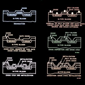
The PLC technology utilizes photolithography to create intricate waveguide patterns on a silica substrate, which results in a high-quality, low-loss device. This technology also allows for a wider operating wavelength range than traditional fused biconical taper splitters. In addition, PLC splitters are more stable and able to operate in a wide range of temperatures, enabling them to work reliably in harsh environments.
Compared to fused biconical taper splitters, PLC splitters have lower insertion loss and more uniform splitting ratios. However, they still suffer from a variety of factors that can affect their performance, such as alignment of the fiber array to the PLC chip, pitch and depth inaccuracies in the v-grooves of the fiber array block that holds the PLC chip, and connector losses.
In order to minimize the insertion loss of PLC splitters, the bare fiber end is coated with an optical fiber. This coating prevents re-spreading of the optical signal and improves connectivity with pigtail cassettes, test instruments, and WDM systems.
Optical Loss
PLC splitter is a passive device in the optical fiber transmission system. It is used to distribute optical signals to multiple ports evenly. It is a component that is important in the construction of FTTH passive optical networks.
The PLC splitter is based on semiconductor technology. It consists of an optical waveguide chip that has been lithography on a silica glass substrate and allows for routing specific percentages of light. It can be assembled into a centralized distribution type and cascaded distribution type.
SANWA offers a range of PLC optical power splitters with different split configurations. They are ideal for use in FTTH construction. They can be installed and mounted into a tray, panel, or enclosure. They can also be directly installed into an ODF frame or optical fiber distribution product. They can accept both MT ferrules and LC connectors.
Optical splitters are vital to passive optical networks (PON) and off-factory FTTX networks. They are the main devices for branching optical signals in a PON network. manufacturing fiber optic passive components In a power-splitting PON, the splitter is located in the outside plant (OLT) to provide an interface for connecting the CO with a feeder fiber, and connects to ONUs by a series of distribution fibers. Compared to FBT couplers, a PLC splitter has a higher splitting ratio and is more reliable.
Wavelength
The PLC Splitter is a semiconductor-based component that uses photolithography on the surface of the substrate to create waveguides. It is mainly used in passive optical networks to connect the central office and terminal equipment. It can perform equal splitting and can also work in reverse to converge multiple input optical signals into single or double outputs. It has the advantages of small size, wide working wavelength range, high reliability, and good optical splitting uniformity.
The 1xN PLC Splitter is the main type of splitter used in passive optical networks. It consists of an optical PLC chip and several multi-channel fiber arrays coupled at both ends of the chip. This design enables up to 128 branches on a single chip. The PLC optical splitter can be divided into two types: bare fiber and blockless types.
Unlike the fused tapered tube (FBT) optical splitter, the PLC optical splitter is not sensitive to wavelength and can support a variety of wavelengths (12601650nm). Its loss is higher than that of FBT optical splitters, but it has the following advantages:
The major problems of the 1xN PLC Splitter include excess insertion losses, fiber array nonuniformity, and connector loss. These problems can be reduced by improving the pitch and depth inaccuracies of the v-grooves on the fiber array block that holds the fiber array and the PLC chip, as well as increasing the quality of the glue.