PLC Splitter
PLC splitter distributes a single fiber signal across multiple connections, maximizing the number of users in a network. It also minimizes the need for amplification, reducing costs and improving performance.
Optical testing includes measuring insertion loss and uniformity for each splitter. These parameters are based on GR-1209 standards to ensure that the splitter meets quality specifications.
Planar Light Circuit (PLC) Technology
Planar Light Circuit splitters regulate the power of optical signals by delivering reliable light distribution. These devices feature a broader operating wavelength range than low-cost fused biconic tapered (FBT) couplers, and they offer enhanced reliability, improved uniformity, and a smaller size. Additionally, they are able to handle high bandwidths, making them a cost-effective alternative to conventional rack-mounted boxes.
The increasing data transmission across several industry verticals is one of the primary factors driving the demand for PLC splitters. This technology helps in optimum transmission of data over long distances without any interruption. Further, it reduces the overall power consumption of optical fiber networks. Additionally, it also offers flexibility in the network design.
A key advantage of PLC splitters is that they are easy to install. They can be used in a variety of network configurations, including in-ground and aerial pedestals, as well as plc-splitter in rack mount systems. They are available in a variety of connector types and finishes, such as FC, SC, ST, and LC. Moreover, they can be used with other devices such as tunable filters or variable attenuators.
To safely transport these devices, the customer required a vacuum-release packaging solution. Gel-Pak worked closely with the customer’s engineering team to understand their process requirements and developed a Large Format Vacuum Release Tray, which allows for lot/wafer traceability. The tray features a gel membrane over a mesh material that immobilizes the device until vacuum is applied. This enables automated Pick & Place (P&P) equipment to remove them without exposing the product to contaminants.
Splitting Ratio
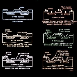
PLC splitter divides a single-mode fiber optical signal into multiple output signals that are evenly distributed. It’s a common component in passive optical networks, providing an efficient and reliable light distribution solution. It can be found in central offices and user-side terminal equipment, as well as in Fiber to the Home (FTTH) networks. Unlike FBT splitters, which fuse multiple fibers together to achieve splitting functions, PLC splitters are built on photolithography technology and use optical waveguides to create branching and distribution functions.
PON splitters have a high splitting ratio and can divide one or two inputs into up to 64 output signals. This allows service providers to conserve backbone optical fibers by using one incoming optical signal to feed many users. It is ideal for FTTH and other applications where space and power are limited.
PLC splitters also have low insertion loss, which is important for achieving optimal performance. They also have excellent temperature stability, which is important for ensuring stable operation in a variety of environments. In addition, they have a wide operating wavelength range of 1260 to 1650 nm, which allows them to be used in a variety of network applications. They are available in a number of different sizes and configurations, including angled and rack-mount types. Moreover, they can be provided in either terminated or unterminated versions to meet the requirements of different projects.
Power Loss
PLC splitter is used in FTTH (Fiber to the Home) networks to divide optical signals from central office to multiple premise locations. It utilizes silica wafer to create a waveguide circuit that divides optical signals into multiple output ports. It also features high reliability and low failure rates. It is widely used in PON(Passive Optical Network), Datacom, LAN(Local Area Networks), CATV(Cable TV) and FTTx (Fiber to the Home).
Insertion loss is an important characteristic for PLC splitters because it indicates how much power is lost during transmission through the device. It is typically measured in decibels (dB) and is specified for each output port. The lower the insertion loss, the better the performance of the splitter.
To test a PLC splitter, attach the meter to the source launch cable and measure the power level at each output port. You can use the insertion loss measurement to determine the quality of the splitter and ensure that it is delivering the correct amount of power to each end user.
There are different types of PLC splitters available, including tray-type and rack-mount splitters. manufacturing fiber optic passive components Each type offers unique advantages. Tray-type splitters are packaged in an integrated splicing tray that can be installed in the ODF distribution frame. Rack-mount splitters are packaged in a 19″ cabinet and typically use an LC or SC connector. They can be easily installed and require less space than LGX cassette splitters.
Installation
PLC splitters are an important part of FTTH (Fiber to the Home) and FTTB (Fiber to the Building) networks. They help to distribute optical signals to end users, reducing network complexity and cost. When properly installed, they provide reliable and high-speed connections for end users. However, the use of incorrect or unsuitable splitter ratios can degrade signal quality and limit scalability. This can lead to shortened reach or network failures.
To ensure proper installation, it is essential to understand the factors that affect splitter performance. These include the splitting ratio, connector type, insertion loss, and operating wavelength. In addition, proper cable management can minimize signal loss and improve reliability. These practices can also simplify network maintenance and troubleshooting procedures.
To install a PLC splitter, first strip the outer jacket of the fiber cable and clean the connectors. It is recommended to use splice trays to prevent dust, debris, and bending that can degrade the signal. Connect the fibers to the input and output ports of the splitter. It is best to use connectors that are qualified to Telcordia GR-326. This ensures that they will perform reliably for decades and through hundreds of matings. It is also necessary to regularly test and maintain the splitter to ensure optimal performance.


