What Is a PLC-Splitter?
A plc-splitter is an important component in FTTH (Fiber to the Home) networks. It is installed between the Optical Line Terminal in the central office and the Optical Network Terminals (ONTs) near end users.
These passive optical devices offer accurate splits with minimal loss in efficient packages. Typically, they are available in bare fiber or connectorized with LC/SC/FC/ST.
Planar Lightwave Circuit (PLC) Technology
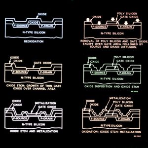
PLC technology uses wafer-scale manufacturing techniques similar to those used in making electronic integrated circuits to process optical signals through a series of waveguides on the same chip. This technology has already established itself as the platform of choice for integrating several functional elements on a single, compact device that can operate over a wide wavelength range.
Currently, planar-lightwave-circuit (PLC) technology is being used primarily for DWDM multiplexer/demultiplexers in which arrayed-waveguide gratings are used to multiplex and demultiplex individual wavelengths within a single optical fiber. However, research demonstrations indicate that multifunction devices based on PLCs are also possible and may soon make the leap from the laboratory to the field.
One example is a PLC-based broadband 2/spl times/2 splitter that can be used in passive optical networks to distribute optical signals from central offices to multiple premise locations. This type of component is critical for enabling PON to realize its potential to provide high-speed, low-cost data and video services over existing fiber. A traditional directional coupler or single-stage Mach-Zehnder can’t deliver such a solution due to its excessive wavelength dependence and lack of channel-to-channel uniformity.
Optical Waveguides
Optical waveguides are optical devices that transmit electromagnetic waves in a medium, such as glass, polymer or semiconductor. They are used in many applications including optical communication, sensing and display technology. Optical waveguides are available in many different shapes, sizes and materials. They can be characterized by their geometry, mode structure and refractive index distribution.
The simplest type of optical waveguide is the dielectric slab waveguide. This consists plc-splitter of two layers of material with different dielectric constants, and light is confined by total internal reflection to paths that lie parallel to the interfaces. The wavelength of a light beam can be tuned by changing the core or cladding material.
For example, a step-index multimode fiber can be converted to a single-mode fiber by increasing the cladding refractive index or decreasing the core refractive index. The normalized wave number, or V-number, of a fiber can be defined as V = kf a NA (where kf is the free space wave number, a is the core radius and NA is the numerical aperture).
Another example of an optical waveguide is the twisted rib-type waveguide. This is made of a core fiber with one strand wrapped around it and then cladded with a second fiber. The resulting symmetrical waveguide has high light delivery performance and is suitable for use in FTTX networks.
Splitting Ratios
Split ratios are used to determine how much of a particular value is shared by each of its parts. The number of parts or shares is determined by adding up the numbers in a ratio and dividing by that total. For example, the ratio 5:45:4 contains 22 parts and 99 shares. The value per share is therefore 49, which is the same as the unit of concentration.
A PLC optical splitter has the ability to transmit a single-mode optical signal from one input fiber to multiple output fibers, resulting in an even distribution of light across all of its ports. These devices are available in a variety of split ratios, including 1X2, 1X4, 1X8, and 1X32. These are ideal for applications such as passive optical network deployments.
Passive Optical Network (PON) technology allows for the sharing of optical fiber networks among many end users. The PON splitting ratio is an important factor in this process, as it determines the number of ONUs that can be connected to a single optical line terminal (OLT). The typical PON splitter has a 1:32 ratio, but new developments are enabling higher split ratios, allowing for more bandwidth and more subscribers to be served by a single OLT.
When using split ratios to control the size of a sample injection, it is important to use the correct one for your application. If the split ratio is too low, there may not be enough gas flow to fully separate and purge the sample. In addition, if the split ratio is too high, it may cause early senescence or cell death.
Applications
Optical signal splitting is an important part of passive optical networks (EPON, GPON, BPON, FTTX) for distributing the signal to multiple terminal equipment and maximizing the number of users. The PLC splitter is a small device that uses planar lightwave circuit technology to divide the optical signals into multiple output channels, which are then transmitted separately.
There are many different types of plc-splitter, including bare fiber splitters, blockless splitters, ABS PLC splitters, LGX box PLC splitters, mini plug-in type splitters, and rack-mount splitters. Each has its own advantages and applications.
The bare fiber PLC splitter is the most basic type and is commonly used in FTTH projects. manufacturing fiber optic passive components It leaves the fiber on all ends and can be easily installed in fiber fusion boxes or fiber distribution frames. It is also a cost-effective option since it requires no filed splicing.
The blockless splitter is a more advanced version of the bare fiber splitter. Its advantage is that it has a stronger and more durable case, which makes it more resistant to damage. Its design also allows it to support more ports, which is ideal for larger networks.


